Digital COD Sensor
User Manual
Table
Attention
1 product configuration
1.1 Standard configuration
1.2 Optional accessories
2 Product introduction
3 Main features
4 Technical indicators
Technical parameters
5 Size Chart
6 Installation and electrical connection
6.1 Standard configuration
Wiring Instructions
7 Use of debugging software
7.1 Communication connection
7.2 Communication connection
7.2.1 Calibration Function
7.2.2 Slave Setting
7.2.3 Factory Reset
7.2.4 Reset address
8 Sensor maintenance
8.1 Maintenance schedule and method
8.1.1 Maintenance schedule
8.1.2 Maintenance method
9 Cautions
Attention
l Please read this manual carefully before use and save it for reference.
l Please follow the operating procedures and precautions in this manual.
l When receiving the instrument, please carefully open the package and check whether the instrument and accessories are damaged due to shipping. If any damage is found, please inform the manufacturer and distributor immediately, and keep the package for return.
l When the instrument fails, do not repair it yourself. Please contact the maintenance department of the manufacturer directly.
1 product configuration
Please confirm the sensor you purchased, the package is completed, if there is any damage to the package or any shortage of accessories, please contact the dealer as soon as possible.The configuration is as follows.
1.1 Standard configuration
² COD sensor ×1
² A user manual ×1
1.2 Optional accessories
² Mounting bracket
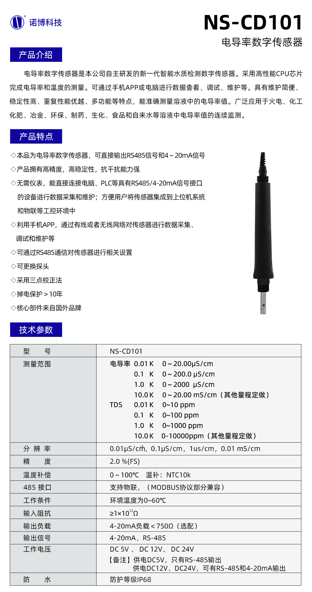
2 Product introduction
Many organic substances dissolved in water absorb ultraviolet light. Therefore, by measuring the absorption of these organic substances by ultraviolet light at a wavelength of 254 nm, the total amount of dissolved organic pollutants in water can be accurately measured. The COD sensor uses two light sources, one ultraviolet light is used to measure the COD content in water, and another reference light is used to measure the water turbidity. In addition, the optical path attenuation is compensated by a specific algorithm and can eliminate particulate suspended matter impurities to a certain extent interference, so as to achieve a more stable and reliable measurement.
3 Main features
² No reagents, no pollution, more economical and environmental protection.
² Small size, easy installation, and continuous water quality monitoring.
² Measure COD, turbidity and temperature parameters.
² Automatic compensation for turbidity interference.
² With a cleaning brush to prevent bio-adhesion.
² Small drift, fast response, more accurate measurement.
² Excellent stability even for long-term monitoring.
² Less aintenance, long service life and low cost of use
² Digital sensor, RS-485 interface, Modbus/RTU protocol.
² Low power design, anti-interference design.
4 Technical indicators
Technical parameters
² Measuring range:
0~200mg/L equiv. KHP (Turbidty 0~100NTU)
0~500mg/L equiv. KHP (Turbidty 0~200NTU)
² Accuracy: COD: ±5%F.S. Turbidity: ±5%F.S.
² Resolution: COD: 0.1mg/L Turbidity: ±5%F.S.
² 485 interface: optically isolated output, partially compatible with MODBUS protocol
² Working conditions: Ambient temperature is 0~60°C
² Input Impedance: ≥1×10¹²Ω
² Power supply: 12~24VDC
² Protection level: IP68
5 Size Chart
6 Installation and electrical connection
6.1 Standard configuration
1. When the sensor is attached, the sensor caused by water flow should be prevented from hitting the wall or other water conservancy facilities. If the water flow is very urgent, fix the sensor.
2.
3. The sensor is placed in a position where there are no bubbles in the water.
4.
l Install a cable protector outside the sensor cable.
l The sensor should be positioned horizontally and securely .The measuring area faces the flow direction.
Wiring Instructions
Red wire: DC12+
Black wire: DC12V-
Yellow wire: RS485 A
Green wire: RS485 B
After wiring is completed, it should be carefully checked to avoid damage to the sensor caused by incorrect wiring.
Cable specification: Considering that the cable is immersed in water (including sea water) for a long time or exposed to the air, the cable has a certain degree of corrosion resistance. The outer diameter of the cable is Φ6 mm and all interfaces are waterproof.
7 Use of debugging software
7.1 Communication connection
Open the debugging software as following:
Select the correct serial port, baud rate, communication interval time, slave number, and click start to communicate.
7.2 Communication connection
7.2.1 Calibration Function
Zero calibration
COD calibration:
1) KHP(Potassium hydrogen phthalate ,C8H5KO4) , As a commonly used stain for environmental research, it can be used for COD calibration.
2) Preparation of standard solution
a. Accurately weigh 0.8503 g of KHP into a 1000 mL flask. Distilled or deionized water and perfused until the highest scale. This solution is a 1000 mg / L COD solution.
b. Take 100 mL of this solution into a 1000 mL flask and fill it to the highest mark with distilled or deionized water. After shaking, the COD concentration was 100 mg/L. A solution having a concentration of 20 mg/L was prepared in the same manner.
c. The concentrated standard solution (step 2.1) was stored in a black glass vial and stored at low temperature to prevent decomposition. The diluted standard (step 2.2) needs to be used within 24 hours of preparation.
3) Calibration (2-point calibration)
a. Calibration of 0-200mg/L measuring range
(1) Put the sensor into 5mg/L COD solution, and confirm that all optical paths are immersed in underwater >2cm and free of bubbles. Wait for the value to be stable. Select the "calibration function" in the "function" menu in the upper left corner, and click the "zero calibration" sub-menu. Enter the COD value of the standard solution in the pop-up dialog box, and click "Send".
(2) Put the sensor into 200mg/L COD solution, wait for the value to be stable. Select the "calibration function" in the "function" menu in the upper left corner, and click the "slop calibration" sub-menu. Enter the COD value of the standard solution in the pop-up dialog box, and click "Send".
b. Calibration of 0-500mg/L measuring range
(1) Put the sensor into 20mg/L COD solution, and confirm that all optical paths are immersed in underwater >2cm and free of bubbles. Wait for the value to be stable. Select the "calibration function" in the "function" menu in the upper left corner, and click the "zero calibration" sub-menu. Enter the COD value of the standard solution in the pop-up dialog box, and click "Send".
(2) Put the sensor into 400mg/L COD solution, wait for the value to be stable. Select the "calibration function" in the "function" menu in the upper left corner, and click the "slop calibration" sub-menu. Enter the COD value of the standard solution in the pop-up dialog box, and click "Send".
Warning:
l KHP is a cancer risk and should be worn with gloves.
l When calibrating, firstly calibrate the temperature, then calibrate the turbidity and then
calibrate the COD.
l If the slope is calibrated, the sensor value does not change within 3 minutes,re-supply after power is cut off.
Turbidity calibration:
1) Zero calibration:
Zero calibration generally uses low-concentration standard solutions (such as distilled water, purified water, etc.) to calibrate the sensor. Select the "calibration function" in the "function" menu in the upper left corner, and click the "Correction calibration" sub-menu, select the correction calibration point number 1. Enter the turbidity value of the standard solution in the pop-up dialog box, and click "Send".
2) Slope calibration
The slope calibration generally uses the range value or a standard solution close to the range value to calibrate the sensor. Select the "calibration function" in the "function" menu in the upper left corner, and click the "Correction calibration" sub-menu, select the correction calibration point number 2. Enter the turbidity value of the standard solution in the pop-up dialog box, and click "Send".
7.2.2 Slave Setting
When the sensors used in a network, the slave ID and baud rate of the sensor may need to be modified. Click the "Slave Settings" sub-menu in the "Function" menu in the upper left corner. In the pop-up dialog box, select the required baud rate, enter the slave number to be set, and click "Send". After successfully modifying the slave ID and baud rate, the debugging software can no longer communicate with the sensor. Now need click the "Stop" button to change the slave ID and baud rate accordingly before communicating with the sensor.
7.2.3 Factory Reset
If the measured value of the sensor is inaccurate due to misoperation and it is inconvenient to re-calibrate, the sensor can be restored to the status before shipment by reset the factory settings. Select "Recovery" in the "Function" menu in the upper left corner, and click the "Factory Settings" sub-menu. Enter the 5-digit password "20034" in the pop-up dialog box, and click "Send". This function will not restore the automatic cleaning interval time, 4-20mA corresponding value, slave number and baudrate.
7.2.4 Reset address
When the user forgets the slave ID and baud rate of the sensor, because the debugging software cannot communicate with the sensor, the functions on the "function " menu cannot be used. At this time, the sensor can be set to slave 1 and 9600 baud rate by resetting the address. This function sends broadcast commands by using the baud rate set in the main interface to achieve the effect of modifying the slave number and baud rate.
1. Select 9600 baud rate and slave number 1 in the main interface, and click "Start".
2. Select the "Reset Address" sub-menu in the "Settings" menu in the upper left corner. In the pop-up dialog box, select 9600 baud rate, enter the slave number 1, and click "Send". Follow the pop-up dialog box to check the wiring and confirm.
3. Still unable to communicate, change the baud rate of the main interface and follow steps 1-2. If all baud rates have been tried, consider troubleshooting the power supply, wiring, and 485 module problems.
8 Sensor maintenance
8.1 Maintenance schedule and method
8.1.1 Maintenance schedule
To ensure accurate measurements, cleaning is important, and regular sensor cleaning helps data stability.
| Maintenance task | Recommended maintenance frequency |
| Calibrate the sensor (if required by the competent authority) | According to the maintenance schedule required by the competent authority |
| Maintain and check the self-cleaning brush | Return to the factory every 18 months for inspection and maintenance of self-cleaning brush |
Note: The maintenance frequency in the above table is only a recommendation. Please maintain the sensor according to the actual usage of the sensor.
8.1.2 Maintenance method
Sensor outer surface: Clean the outer surface of the sensor with tap water. If there is still debris left, wipe it with a soft, damp cloth. For some stubborn dirt, add some household washing liquid to the tap water to clean it.
1) Check the cable of the sensor: the cable should not be tightened during normal operation. Otherwise, the cable inside the cable may be broken, causing the sensor to malfunction.
2) Check if the sensor's measurement window is dirty and the cleaning brush is normal.
3) Check the sensor's cleaning brush for damage.
4) For 18 months of continuous use, it is necessary to return to the factory to replace the dynamic sealing device.
9 Cautions
The sensor contains sensitive optical and electronic components. Please ensure that the sensor is not subjected to severe mechanical impact. There are no parts inside the sensor that require user maintenance.